
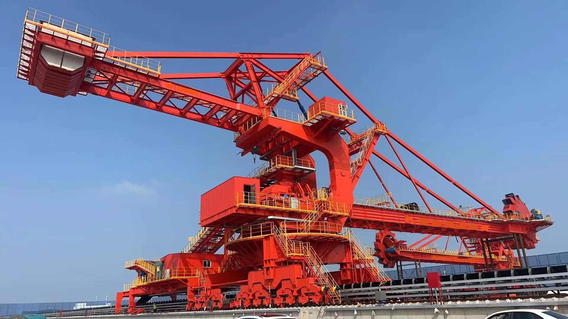


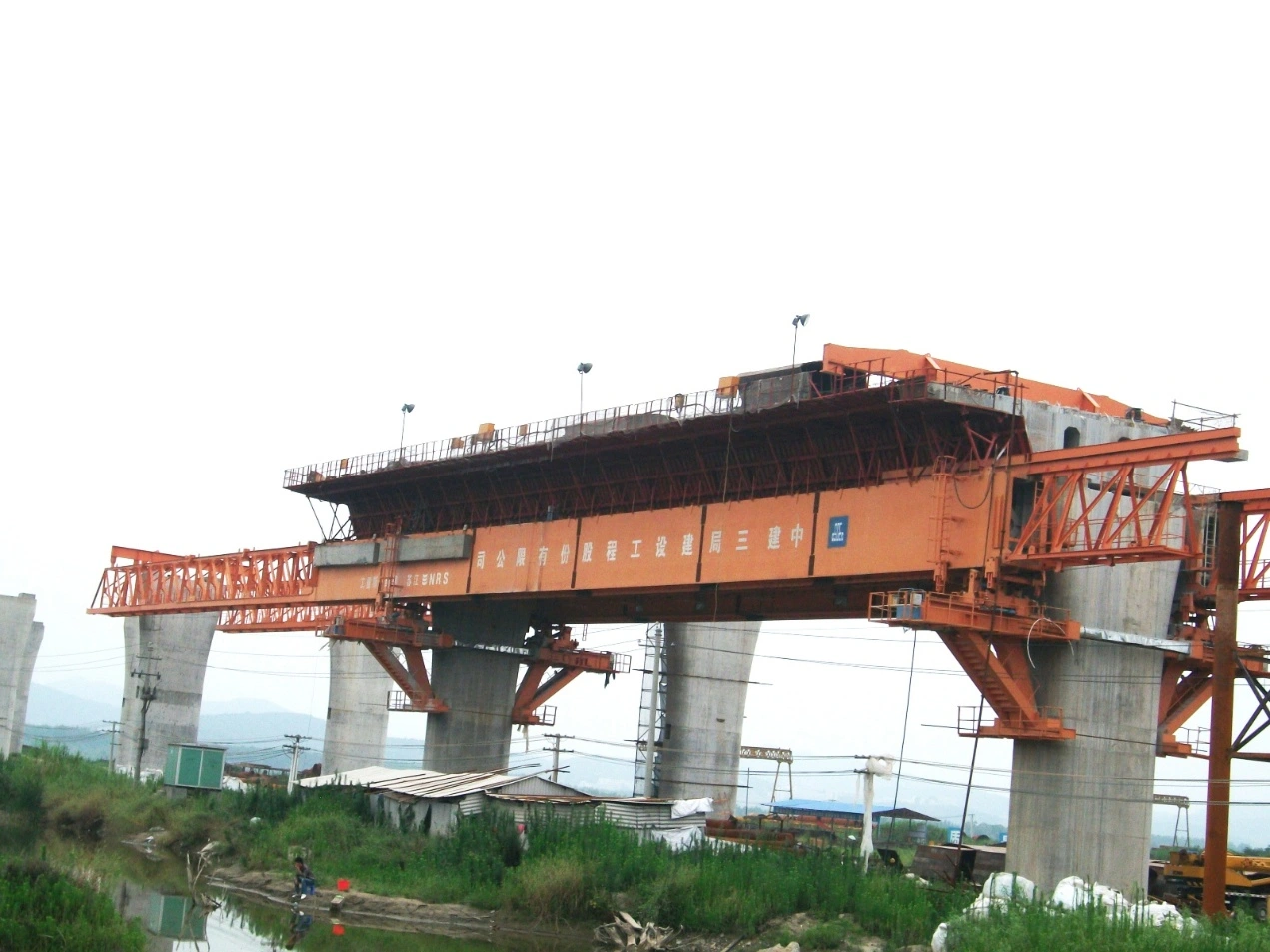

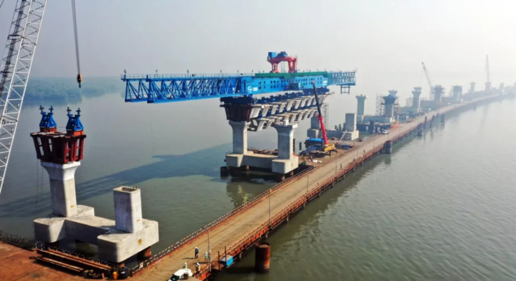
A lansering av gantri is a specialized bridge construction equipment designed for incremental bridge deck installation in elevated highway and railway projects. This mobile steel truss structure revolutionizes repetitive span construction by eliminating ground-level scaffolding and enabling continuous deck segment placement at heights exceeding 50 meters. Widely adopted in Asia-Pacific and European infrastructure corridors, launching gantries reduce construction timelines by 30-40% compared to traditional falsework methods while maintaining superior safety standards. This comprehensive guide explores the technical principles, operational mechanisms, and commercial advantages of launching gantry systems in modern infrastructure development, providing procurement decision-makers with critical evaluation criteria for equipment selection.
Understanding Launching Gantry Technology
Definisjon og kjernekomponentar
A launching gantry functions as a self-propelled bridge-building factory, consisting of a longitudinal steel truss framework that spans between completed piers to cast or install successive deck segments. The system comprises four essential structural elements:
Primary Load-Bearing Components:
- Main Girder Assembly: Twin parallel trusses (typically 3-5 meters deep) spanning 40-65 meters, fabricated from high-strength Q345 or Q420 steel with welded box-section construction
- Front Support Legs: Hydraulically adjustable vertical towers (8-15 meters height range) that anchor onto the newly completed deck segment
- Rear Support Legs: Fixed-height supports resting on the previously cast span, maintaining longitudinal stability during concrete placement
- Transverse Form Traveler: Suspended formwork carriage housing steel molds, concrete distribution systems, and vibration equipment
Operational Systems:
- Synchronized hydraulic jacking units (200-400 ton capacity per point)
- Longitudinal sliding rail assemblies with PTFE-coated bearing pads
- Electrical control cabinets featuring PLC-based positioning algorithms
- Integrated safety interlocks prevent movement during concrete curing phases
Modern systems incorporate laser-guided alignment sensors maintaining positional accuracy within ±3mm tolerance, critical for precast segment matching or cast-in-place deck continuity.
Technical Classification and Variants
Overhead Type Launching Gantry: The truss structure travels atop the completed deck, with formwork suspended below. This configuration dominates in projects with 30-45 meter spans and deck widths up to 18 meters. Load capacity ranges from 800 to 1,200 tons, accommodating standard box-girder cross-sections. The overhead design provides unobstructed ground clearance, essential for crossing active railways or waterways.
Underslung Type Launching Gantry: Employed in longer spans (45-60 meters) or situations requiring reduced vertical clearance. The main truss operates below deck level, supported by cantilevered brackets from pier caps. This variant handles 600-900 ton loads and proves advantageous in urban environments with overhead utility conflicts.
Span Capacity Classifications:
- Light-Duty Systems (30-40m spans): 600-800 ton capacity, typical cycle weight 450-650 tons
- Medium-Duty Systems (40-50m spans): 800-1,000 ton capacity, accommodating 650-850 ton concrete pours
- Heavy-Duty Systems (50-65m spans): 1,000-1,400 ton capacity, specialized for high-speed rail viaducts with reinforced deck sections
Load-bearing specifications must account for dynamic factors, including concrete slump flow (typically 180-220mm for self-consolidating mixes), construction live loads (150 kg/m² minimum), and wind-induced lateral forces during the 18-36 hour curing window.
How Launching Gantry Systems Operate
Step-by-Step Construction Process
The incremental launching methodology follows a precise seven-stage cycle optimized for 5-7 day repetition intervals:
Stage 1 – Positioning (Day 1, 6-8 hours): After completing the previous span’s concrete curing, hydraulic jacks elevate the gantry 50mm above sliding rails. Synchronized electric winches advance the entire assembly forward one span length, guided by laser total stations, maintaining alignment within 5mm horizontal and 3mm vertical tolerances.
Stage 2 – Support Transfer (Day 1, 2-4 hours): Front support legs extend hydraulically to contact the newly completed deck segment. Load cells verify uniform bearing pressure (typically 8-12 MPa on reinforced concrete) before locking mechanisms engage. Rear legs simultaneously retract and reposition on the previous span.
Stage 3 – Formwork Preparation (Day 2, 8 hours): Technicians assemble bottom slab forms, adjust web formwork panels, and install pre-positioned rebar cages (delivered via gantry-mounted crane). External vibrator mounts attach to form surfaces at 2-meter intervals.
Stage 4 – Concrete Placement (Day 3, 6-10 hours): Concrete pumps deliver 300-500 m³ of C50-C60 grade concrete through distribution booms. Placement proceeds in three lifts (bottom slab → webs → top slab) with 45-60 minute intervals, allowing initial set. Real-time temperature monitoring prevents thermal cracking in thick sections.
Stage 5 – Curing and Monitoring (Days 4-6): Automated curing systems maintain 95%+ humidity via fogging nozzles. Embedded maturity sensors track concrete strength development, with 75% design strength (typically 30-35 MPa) required before launching authorization.
Stage 6 – Form Stripping (Day 7, 4-6 hours): Hydraulic form release systems separate molds from cured concrete. Inspection teams verify surface finish quality and dimensional compliance before certifying span completion.
Stage 7 – System Reset: The gantry returns to Stage 1 positioning for the subsequent span. Optimized crews achieve 52-week construction rates of 45-55 spans on projects with minimal weather delays.
Hydraulic Launching Mechanism
The longitudinal advancement system employs redundant hydraulic circuits, ensuring fail-safe operation during the critical translation phase:
Jacking System Architecture: Four to eight synchronized hydraulic cylinders (250mm bore, 300mm stroke) mount at strategic truss nodes. Proportional valve banks maintain pressure equilibrium within 2 bar across all jacks, preventing torsional stress. Total jacking force ranges from 800 to 1,600 kN depending on gantry mass (typically 350-600 tons) and rail friction coefficients (0.05-0.08 for greased steel-on-PTFE interfaces).
Sliding Rail Configuration: Continuous steel rails (UIC 60 or equivalent profiles) embedded in the deck’s top surface, aligned to ±2mm over 60-meter spans. Bearing assemblies incorporate self-lubricating composite pads (PTFE/bronze matrix) rated for 15 MPa contact pressure. Rail heating systems prevent ice formation in cold climates, maintaining consistent friction characteristics.
Precision Alignment Controls: Dual-axis inclinometers (0.01° resolution) and laser distance sensors provide real-time position feedback to the PLC controller. Automated correction algorithms adjust individual jack extensions, compensating for thermal expansion differentials or pier settlement irregularities. Emergency stop systems activate if lateral deviation exceeds 8mm or longitudinal speed surpasses 3 meters/minute.
Launching Gantry vs. Traditional Scaffolding Comparison
| Performance Dimension | Fråsegleport | Traditional Scaffolding |
|---|---|---|
| Construction Speed | 5-7 days per 40m span | 12-18 days per span |
| Safety Rating | 0.3 accidents/million man-hours | 2.1 accidents/million man-hours |
| Labor Requirements | 18-25 workers per crew | 45-60 workers per span |
| Cost per Span | $85,000-$120,000 (amortized) | $140,000-$190,000 |
| Environmental Impact | Zero ground disturbance | Extensive site clearing required |
| Height Limitation | Effective to 80m elevation | Economically limited to 35m |
Engineering Standards and Compliance
International Design Codes
EN 1090-2:2018 Structural Steel Execution: Governs fabrication tolerances for gantry truss members, mandating ±3mm dimensional accuracy for connections exceeding 2 meters. Welding procedures require qualification per ISO 15614, with 100% ultrasonic testing of primary load-path welds. Material certificates must demonstrate Charpy V-notch toughness ≥27J at -20°C for components operating in temperate climates.
AASHTO LRFD Bridge Design Specifications (9th Edition): Section 10 addresses temporary works loading, stipulating 1.25 safety factors for construction equipment dead loads and 1.75 factors for dynamic concrete placement forces. Launching gantries supporting precast segments must demonstrate a 2.0:1 factor against overturning under 50-year wind events.
ISO 9001:2015 Quality Management: Reputable manufacturers maintain certified QMS covering design validation, material traceability, and load testing protocols. Third-party inspection agencies verify 125% proof load testing before initial deployment, with annual recertification inspections documenting structural integrity.
Safety and Operational Standards
Wind Load Limitations: Operations cease when sustained winds exceed 13 m/s (Beaufort Scale 6), or gusts reach 18 m/s. Anemometers mounted on gantry peaks trigger audible alarms at an 11 m/s threshold, allowing 20-minute shutdown procedures. Permanent installations in typhoon-prone regions incorporate retractable wind shields, reducing effective surface area by 40%.
Seismic Design Considerations: Projects in Seismic Design Categories C-E require dynamic analysis demonstrating gantry stability during 0.3g horizontal accelerations. Base isolation systems using elastomeric bearings decouple the gantry from pier vibrations, preventing resonance amplification. Emergency braking systems engage automatically upon detecting ground motion exceeding 0.05g.
Operator Certification: Control cabin personnel must complete 80-hour training programs covering hydraulic system diagnostics, concrete placement sequencing, and emergency response protocols. Annual recertification includes simulated failure scenario drills and written examinations on updated safety bulletins.
Commercial Applications and Project Suitability
Ideal Project Scenarios
Elevated Highway Viaducts: Launching gantries achieve optimal economics on grade-separated expressways featuring 12+ continuous spans with 35-50 meter pier spacing. The Hangzhou Bay Bridge approach viaducts (China) utilized twin gantries to complete 8.2 kilometers of elevated roadway in 26 months, demonstrating 60% faster delivery than bid alternatives.
Cross-Valley Railway Bridges: High-speed rail projects requiring minimal ground disturbance favor underslung gantries. The Taiwan High-Speed Rail employed specialized 55-meter span systems across environmentally sensitive mountain valleys, eliminating 180,000 m³ of temporary earthworks.
Urban Overpasses: Congested metropolitan areas benefit from gantry systems’ compact footprint. The Delhi Metro Phase III utilized overhead-type gantries operating above active traffic corridors, maintaining 4-lane flow while constructing 23 kilometers of elevated guideway.
Minimum Economic Threshold: Break-even analysis indicates 8-10 repetitive spans justify dedicated gantry procurement. Projects with fewer spans achieve better value through rental arrangements or alternative methods like balanced cantilever construction.
ROI and Procurement Considerations
Capital Investment Analysis:
- Entry-Level Systems (30-40m spans, 600-ton capacity): $800,000-$1,200,000
- Mid-Range Systems (40-50m spans, 900-ton capacity): $1,500,000-$2,200,000
- Heavy-Duty Systems (50-60m spans, 1,200+ ton capacity): $2,400,000-$3,500,000
Break-Even Calculation: A $1.8M gantry amortized over 60 spans yields $30,000/span equipment cost. When combined with reduced labor ($45,000 savings/span) and schedule acceleration benefits (liquidated damages avoidance), payback occurs at span 18-22 for most contractors.
Rental vs. Purchase Decision Matrix:
- Purchase Recommended: Multi-year project portfolios exceeding 40 cumulative spans; in-house maintenance capabilities; regional market allowing post-project resale at 55-65% original value
- Rental Optimal: Single projects under 25 spans; first-time gantry users requiring vendor technical support; markets with established equipment leasing infrastructure ($45,000-$75,000/month typical rates)
FAQ Module
Q1: What is the minimum bridge length that justifies launching gantry investment?
Economic viability begins at 8-10 repetitive spans (320-500 meters total length for 40m span configurations). Contractors should calculate the total cost of ownership, including mobilization ($80,000-$150,000), operator training, and demobilization against alternative methods. Projects under this threshold often achieve better value through precast beam erection or incremental launching of complete superstructures.
Q2: How does the weather affect launching gantry operations?
Wind represents the primary constraint, with operations suspended above 13 m/s sustained velocities. Rain delays concrete placement only during heavy downpours (>15mm/hour) that compromise mix quality. Temperature extremes require mitigation: cold weather (<5°C) demands heated enclosures and accelerated cement, while hot conditions (>35°C) necessitate chilled mixing water and evaporation retarders. Tropical monsoon climates may reduce annual productivity by 15-20% compared to temperate regions.
Q3: Can launching gantries accommodate curved bridge alignments?
Modern systems handle horizontal curves to 600-meter radius through adjustable support leg geometry and articulated main girder connections. Tighter curves (400-600m radius) require specialized steering mechanisms, adding 12-18% to base equipment cost. Vertical curves present greater challenges, with maximum grade changes limited to 3-4% between adjacent spans without auxiliary jacking systems. Combination horizontal-vertical curves demand project-specific engineering analysis.
Launching gantry technology represents the optimal solution for repetitive span construction in elevated bridge projects, offering superior safety, speed, and cost-efficiency compared to conventional falsework methods. The methodology’s 40-year evolution has produced highly refined systems capable of 5-day construction cycles while maintaining stringent quality standards. Proper equipment selection requires careful analysis of project-specific parameters, including span configuration (economic threshold at 8+ spans), site constraints (wind exposure, seismic risk), and long-term construction portfolio considerations. Contractors investing in gantry systems typically realize 25-35% total cost savings on qualifying projects while reducing schedule risk and enhancing worker safety metrics. As global infrastructure demand intensifies, launching gantry adoption continues expanding beyond traditional Asian and European markets into North American and Middle Eastern bridge construction sectors.